1. Getting Started with the AmebaZ2
The amebaz2 board is able to use the amazon-freertos sdk version 1.4.7. The AmebaZ2 board is designed by Realtek and is a Wi-Fi ready chip.
1. Hardware Requirement
The hardware components needed to test the amazon-freertos are listed below:
a. AmebaZ2 Dev Board Version DEV_2V0
It is required to have the AmebaZ2 Dev board in order to run the amazon-freertos SDK. The current demo board version is: DEV_2V0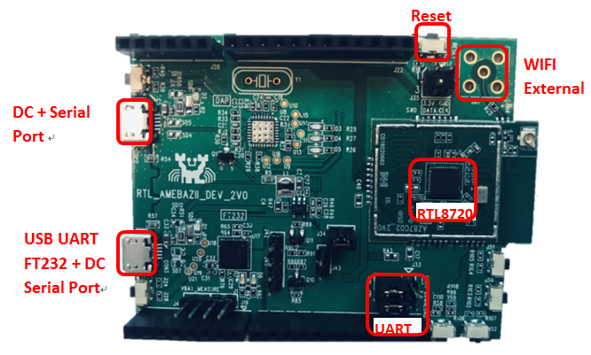
b. J-Link/J-Trace Debug Probe
In order to program and download the software onto the AmebaZ2 board, a JLINK/JTRACE debugger device is needed. More details about the J-Link probe can be found here:
https://www.segger.com/products/debug-probes/j-link/
2. Supported Development Environment.
Currently the amazon-freertos is supported by the IAR Embedded Workbench ver.8.30.1. For windows operating system only.
3. Pre-Requisite
- Required source code
- AmebaZ2 Dev Board DEV_2V0
- IAR Embedded Workbench ver.8.30.1
- Segger JLINK downloader
2. Pre-Requisites & Set-Up
To download code or debug on Ameba-ZII, user needs to make sure the debugger is setup properly first. Ameba-ZII supports J-Link for flahing and debugging. The settings are described below. Since the DEV_2V0 board supports only the JLINK debugger we shall be highlighting the JLINK setup first.
2.1. J-Link Setup
Ameba-ZII supports J-Link debugger. We need to connect the SWD connector to J-Link debugger. The connection is shown as below.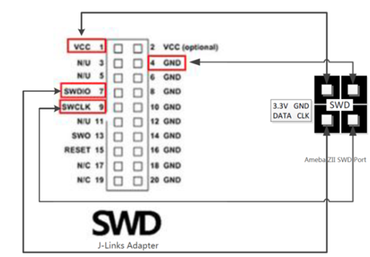
Note: To be able to debug Ameba-ZII which is powered by Cortex-M33, user needs a J-Link debugger with the latest hardware version (Check
https://wiki.segger.com/Software_and_Hardware_Features_Overview for details). J-Link with hardware version V10 is used to prepare this document.
The SWD connectors on the actual dev board are seen on the schematic as shown below: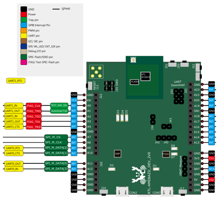
After finished these configuration, please connect it to PC side.
Note: If you are using Virtual Machine as your platform, please make sure the USB connection setting between VM host and client is correct so that the VM client can detect the device.
2.2. Windows Setup
To be able to use J-Link debugger, you need to install J-Link GDB server first. For Windows, please check http://www.segger.com and download “J-Link Software and Documentation Pack” ( https://www.segger.com/downloads/jlink ). Run the executable “JLinkGDBServer.exe” to setup the configuration for the J-Link debugger. Make sure the configuration matches what is shown below: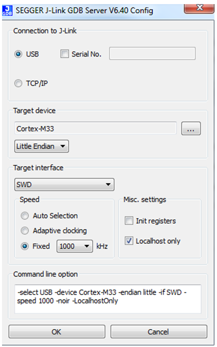
Please check and make sure below information is shown properly.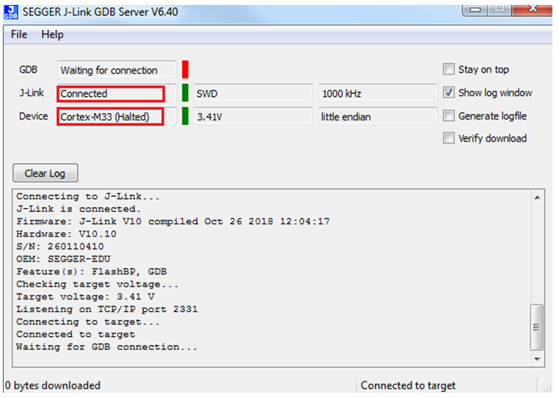
2.3. Serial Port Setup
Connect the AmebaZII to your PC by connecting a microUSB cable between connector ‘CON3″ and your PC. This connector can be seen on the schematic shown previously. The connector acts as both the serial port and the power supply to the board.
2.4. IAR Project Introduction
IAR IDE provides the toolchain for Ameba-ZII. It allows users to write programs, compile and upload them to your board. Also, it supports step-by-step debugging. User can visit the official website of IAR Embedded Workbench, and install the IDE by following its instructions. The IAR Embedded Workbench requires a license, more details can be found at: https://www.iar.com/iar-embedded-workbench/#!?currentTab=free-trials
Note: Please use IAR version 8.30 or above.
3. Build and Run the FreeRTOS Demos
All the amazon-freertos demo files are already built into the project file present in the folder: “amazon-freertos\demos\realtek\amebaz2\iar”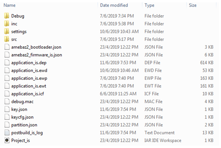
The project file is named “project_is.eww” and the application_is.ewp is already pre-configured with all the necessary files, pre-build and post-build scripts.
3.1.1 Project Configurations
1) There are a lot of configurations that can be enabled or disabled from the file “platform_opts.h”
2) The default version will run the baseline software along with the amazon-freertos demos.
3) The aws hello world example will run by default.
3.1.2 Compile
1) Open amazon-freertos\demos\realtek\amebaz2\iar \Project_is.eww.
2) Confirm application_is in Work Space, right click application_is and choose “Rebuild All” to compile.
3) Make sure there are no errors after compilation.
3.1.3 Generating image binary
After compilation, the images partition.bin, bootloader.bin, firmware_is.bin and flash_is.bin can be seen in the EWARM-RELEASE\Debug\Exe.
1) partition.bin stores partition table, recording the address of Boot image and firmware image;
2) bootloader.bin is bootloader image;
3) firmware_is.bin is application image;
4) flash_is.bin links partition.bin, bootloader.bin and firmware_is.bin. Users need to choose flash_is.bin when downloading the image to board by PG Tool.
3.1.4 Download
After successfully compiling the project and generating flash_is.bin, you can either:
1) Directly download the image binary on to demo board from IAR IDE (as below)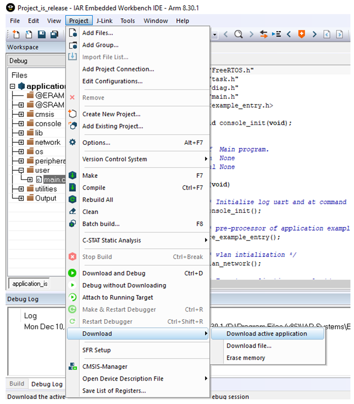
2) Once the image is successfully downloaded, the dev board needs to be reset in order to be able to run the application and see the logs.
3) Once the reset button is pushed the board will boot and run the demo program chosen.
3.1.5 Debugging
1) IAR can be used for debugging purposes. The debugging confirmations are already built into the project file
2) Open up IAR and go to Project and select your debug option.