Please download the library: AmebaMotors
And add the library to Ameba: https://www.arduino.cc/en/Guide/Libraries#toc4
Preparation
- Ameba x 1
- L298N H-Bridge x 1
- 4-wheel motorcar or 2-wheel motorcar+Universal wheel
L298N is used to control the motor module.
We use 4-wheel motorcar in this example. A typical 4-wheel motorcar set usually contains:
- 4 DC motors
- 4 wheels
- Car body
- 4 Speed Encoders
For example:
http://www.ebay.com/itm/4WD-Robot-Smart-Car-Chassis-Kits-car-with-Speed-Encoder-DC-3v-5V-6V-for-Arduino-/171122633517
http://www.dx.com/p/arduino-compatible-bluetooth-controlled-robot-car-kits-146418#.Vtf6J_l96Uk
http://goods.ruten.com.tw/item/show?21550316391242
Materials
- DC Motors
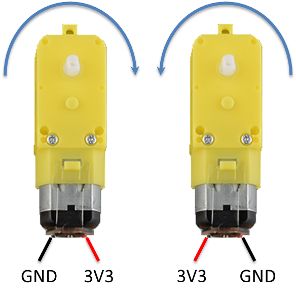
Ordinary DC motors uses two wires to control the rotation. As shown in the figure below, when we connect L to GND, R to 3V3, the motor starts to rotate. And if we connect L to 3V3, R to GND, the motor starts to rotate in the opposite direction. If we change 3V3 to 5V, the motor would rotate in a higher speed. Please refer to spec to find the maximum acceptable current of the motor.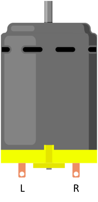
The figure below shows a typical DC motor, you can find a side with a protrusion to install the wheel.
- L298N H-Bridge
Typical L298N modules in market contain these pins: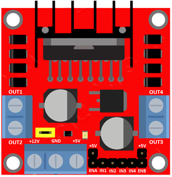
- +12V: Power supply for L298N. Common acceptable voltage range: +6V~+12V, +5V~+12V, +7V~+12V, >=+12V
- GND: Connect to GND of power.
- +5V: If connected power supply of L298N is larger than +7V, the +5V pin can supply power to other components (EX. Ameba). There is a jumper above +12V, connect the Jumper to provide +5V.
- OUT1, OUT2: The output pins to control the first motors set (control at most 2 motors at a time).
- OUT3, OUT4: The output pins to control the second motors set.
- ENA, IN1, IN2: Input pins to control the output to OUT1 and OUT2.
- ENA is used to control the rotation speed of the first set of motors (usually via PWM).
- IN1&IN2 are used to control the rotation direction of the first motors set:
IN1 IN2 OUT1 OUT2 LOW LOW LOW LOW HIGH LOW HIGH LOW LOW HIGH LOW HIGH
- ENB, IN3, IN4: Input pins to control the output to OUT3 and OUT4.
- ENB is used to control the rotation speed of the second set of motors (usually via PWM).
- IN3&IN4 are used to control the rotation direction of the second motors set:
IN3 IN4 OUT1 OUT2 LOW LOW LOW LOW HIGH LOW HIGH LOW LOW HIGH LOW HIGH
Example
We will use the following pins in the example:
| ENA | IN1 | IN2 | IN3 | IN4 | ENB |
| 8 | 9 | 10 | 11 | 12 | 13 |
Wiring: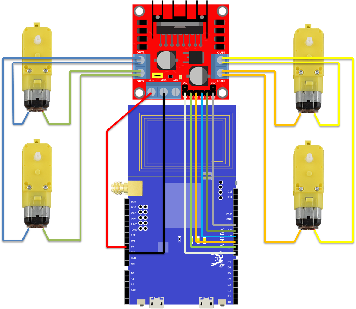
Note:
- We connect Ameba 5V to L298N +12V to supply power. However, not every L298N accepts 5V power supply, if this does not work, please connect L298N +12V to other power supply (e.g., +12V) and use L298N +5V to supply power to Ameba.
- The correct wiring of the motor depend on each model (may be opposite). Please run the test program first, make sure it runs correctly before assembling the motorcar.
- For convenience purposes, it’s recommended to use dupont line to organize the wiring of motors and L298N.
Everytime you modify your program, please remember to unplug the power of L298N to avoid the motor running unexpectedly. Connect Ameba to power, upload the program, and then connect L298N to power when you are going to test the proram.
Compile and upload the “car2wd_digital_control” example to Ameba.
In this program, we make the motorcar to perform following moves:
Move forward 2s => Stop 1s => Move backward 2s => Stop 1s => Rotate in clockwise direction 2s => Stop 1s => Rotate in counterclockwise direction 2s => Stop 1s => Move forward and turn right then turn left => Stop 1s => Move forward and turn left then turn right => Stop 1s => ……
Next we describe the control of the motorcar in the following:
- Speed: We control ENA and ENB via PWM, frequency is fixed at 200 (resolution=256).
- Move Forward:
IN1 IN2 IN3 IN4 HIGH LOW HIGH LOW - Move Backward:
IN1 IN2 IN3 IN4 LOW HIGH LOW HIGH - Clockwise Rotation: Control the left-side motor to move forward, and right-side motor to move backward:
IN1 IN2 IN3 IN4 HIGH LOW LOW HIGH - Counterclockwise Rotation: Control the right-side motor to move forward, and left-side motor to move backward:
IN1 IN2 IN3 IN4 LOW HIGH HIGH LOW - Move forward and turn right: There are two ways to perform this movement.
- First, let the motors on left-side and the motors on right-side to rotate in different speed. However, considering the quality of the wheels of motorcar set, this approach may not work as we expect.
- Second, we let the motors on one side to run and stop in turn. This approach works on most models of motorcars.
Firsr, set the motor to move forward:IN1 IN2 IN3 IN4 HIGH LOW HIGH LOW Then we set the IN3 pin to LOW for 80ms, then HIGH for 20ms, then LOW for 80ms, and so on.
Move forward and turn left, move backward and turn left/right are also done in a similar way.
If the program functions correctly, you can assemble the motorcar.
Below is the demo video of this example:
Code Reference
- Control GPIO in register level
Since we need to control the motor in real-time, we need to control GPIO in register level. (High-level API provided by Arduino, e.g.,digitalWrite(), requires long reaction time. )- First, GPIO setting:
pinMode(in3, OUTPUT); - Next, keep the port and the bit mask of this GPIO pin in mind. Usually the input, ouput or other control bit of GPIO would be in the same register. The port stands for the corresponding register of the GPIO we want to control. The bit mask is used to identify the bit we want to control.
in3_port = digitalPinToPort(in3);  // Get the port of in3
in3_bitmask = digitalPinToBitMask(in3);  // Get the bit mask of in3
- Controlling GPIO
// Set the output port of in3 to 1, now in3 is HIGH
*portOutputRegister(in3_port) |=  in3_bitmask;
// Set the output port of in3 to 0, now in3 is LOW
*portOutputRegister(in3_port) &= ~in3_bitmask;
- First, GPIO setting:
