Introduction of GPIO
- We can use GPIO (General Purpose Input/Output) to control the input and output signal of a board. In the input case, GPIO reads the input signal, and depends on the voltage, GPIO decides whether the signal represents value 0 or 1.
- In the output case, GPIO outputs its operating voltage when we set GPIO to 1. Take Ameba as an example, it outputs 3.3V when the GPIO is set to 1. Otherwise, if we set GPIO to 0, it outputs 0V.
Materials
- Breadboard x 1
- Ameba x 1
- LED x 1
- 1 KΩ Resistor x 1
- Button x 1
Example
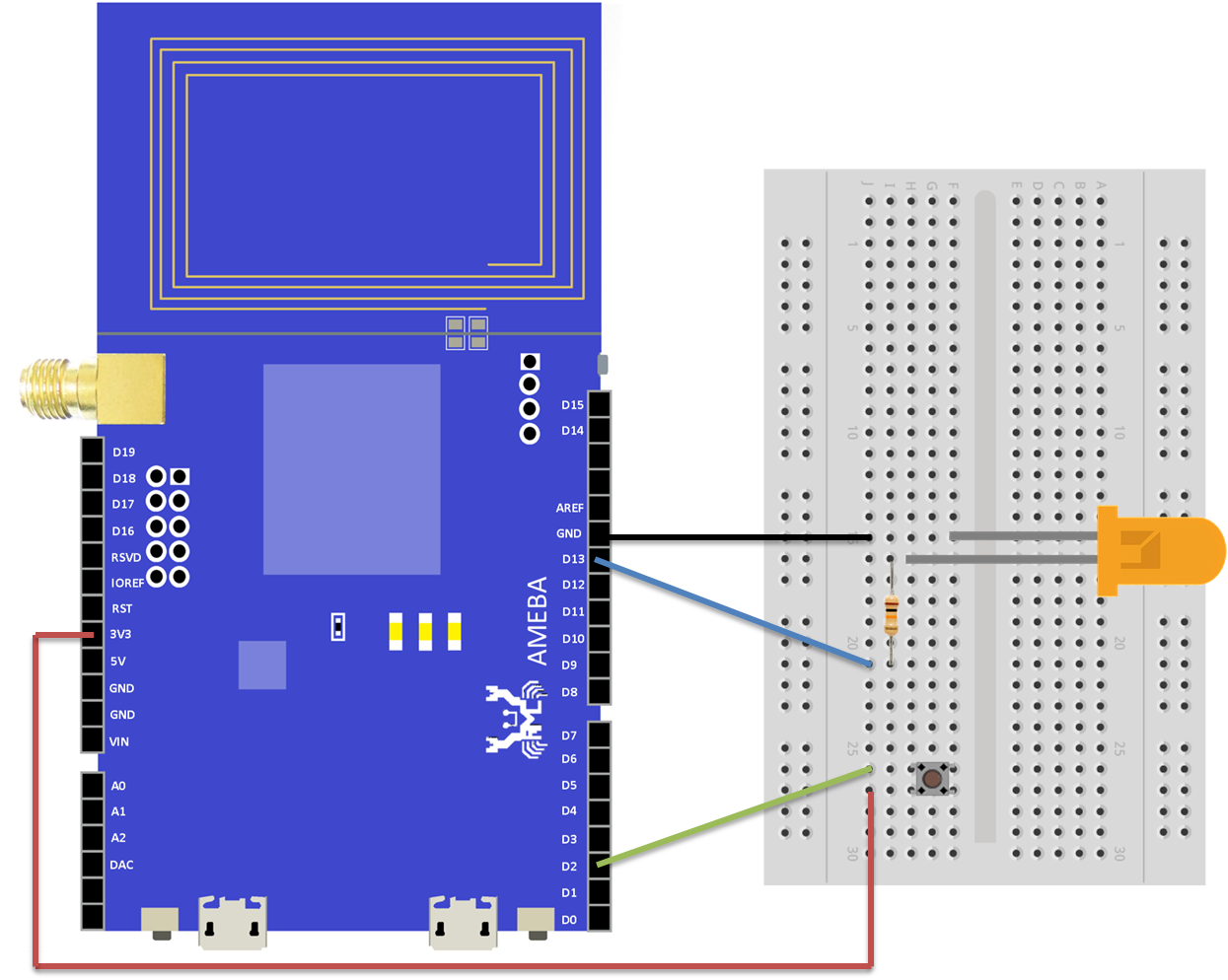
First, we use D2 as GPIO input. Please connect one end of the button to D2, and connect the other end to 3V3.
Next, we use D13 as GPIO output. Please connect the LED to D13.
When we press the button, GPIO input (D2) reads value 1, then we set GPIO output (D13) to 1, so as to make the connected LED lights.
For more information, please refer to the documentation of this example on the Arduino website:
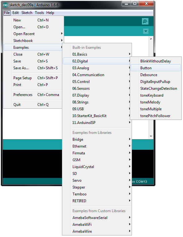
https://www.arduino.cc/en/Tutorial/Button Open the “Button” example in “File” -> “Examples” -> “02.Digital” -> “Button”
Note that in the documentation, the button is connected to 5V, because the operating voltage of Arduino is 5V. However, the operating voltage of Ameba is 3.3V, so we should connect the button to 3V3.
In an LED, the longer pin is the positive pole, and the shorter pin is the negative pole. Therefore, we connect the shorter pin to GND (voltage is 0), and the longer pin to D13. Additionally, to avoid the electric current exceeds the tolerance of the LED and causes damage, we connect a resistance on the positive pole.
Finally, when we press the button, the LED lights. And when we release the button, the LED dims.
Code Reference
we use pinMode(pin, mode) to configure the specified pin to behave either as an input or an output:
https://www.arduino.cc/en/Reference/PinMode
and use digitalRead(pin) to read the value from a specified pin, and returns HIGH or LOW:
https://www.arduino.cc/en/Reference/DigitalRead
use digitalWrite(pin, value) to write a HIGH or a LOW value to a digital pin:
https://www.arduino.cc/en/Reference/DigitalWrite
Comparison with Arduino
According to the documentation on the Arduino website, the GPIO input of Arduino is set to “floating” by default. In other words, before the button is pressed, the input is not connected to anything, therefore the GPIO input is not able to determine the value of input, so the value will be “floating”. As a result, the LED may light when we are not pressing the button.
To solve this problem, we can set the GPIO input to GND (“pull down”) or 3V3 (“pull up”) when the input pin is not connected to anything. This approach is called “Internal Pull Down/Up”.
Another solution is to connect one end of a resistor with large resistance (10M) to the GPIO pin, and connect the other end to GND or 3V3. This approach is called “External Pull Down/Up”. By default, Ameba uses the “Internal Pull Down/Up” approach to avoid this problem, that is to say, when the GPIO pin is not connected, it reads the input value 0.
