Preparation
- Ameba x 1
OTA
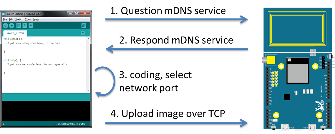
(i) Arduino IDE searches via mDNS for devices with Arduino IDE OTA service in local network.
(ii) Since mDNS service is running on Ameba, Ameba responds to the mDNS search and opens the specific TCP port for connection.
(iii) User develops program in Arduino IDE. When complete, choose network port.
(iv) Click upload. Then Arduino IDE sends the OTA image to Ameba through TCP, Ameba saves the image to specific address and sets boot option to boot from this image next time.
In the next section, we will discuss on how to process the OTA image, and introduce some basic knowledge on Ameba flash memory layout and boot flow.
Ameba Flash Memory Layout
As shown in the figure below, Ameba program occupies three parts of the flash memory:
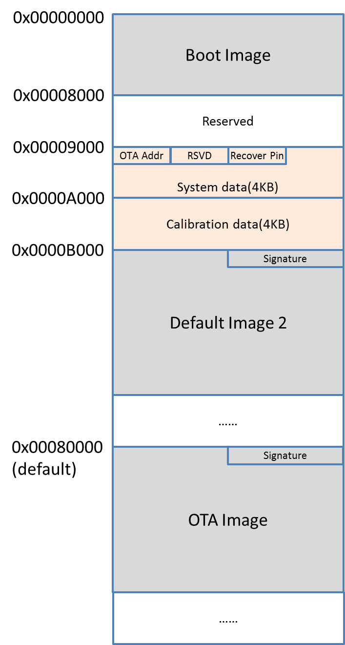
– Boot Image:That is, the bootloader. When Ameba boots up, it places the boot image to memory and performs initialization. Furthermore, it determines where to proceed after the bootloader. Bootloader looks at the OTA address and recovery pin in system data area and determines which image will be executed afterwards. At the end of the bootloader, it places the image to memory and prceeds to execute it.
– Default Image 2:The developer code is placed in this part, the address starts from 0x0000B000. The first 16 bytes are the image header, 0x0000B008~0x0000B00F comprises the Signature, which is used to verify whether the image is valid. The signature field has two valid values to distinguish the new image from the old image.
– OTA Image:The data in this part is also developer code. By default, this part of memory starts from 0x00080000 (can be changed). The main differences between OTA image and Default Image 2 are the flash memory address and Signature value.
Apart from the code, there are some data blocks:
– System Data:
System data block starts from 0x00009000. There are two OTA-related data:
1. OTA address:4 bytes data starting from 0x00009000. It tells the OTA Image address. If the OTA address value is invalid (i.e., 0xFFFFFFFF), the OTA image in flash memory cannot be loaded correctly.
2. Recovery Pin:4 bytes data starting from 0x00009008, The recovery pin is used to determine which image (default Image 2 or OTA Image) to execute when both image is valid. If the recovery pin value is invalid (i.e., 0xFFFFFFFF), the new image will be executed by default.
System data will be removed when we upload program to Ameba via DAP. That is, the OTA address will be removed and Ameba will determine there is no OTA image.
– Calibration Data:The peripheral calibration data is placed in this block. Normally these data should not be deleted.
Boot Flow
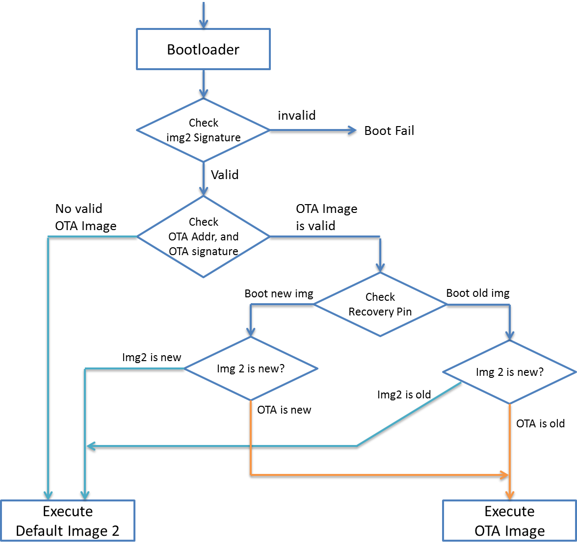
We discuss the following scenarios:
(i) OTA is not used, use DAP to upload program:
In this situation, bootloader checks the signature of default image 2 and OTA address. Since the OTA address is removed, default image 2 will be selected to execute.
(ii) OTA image is transferred to Ameba, OTA address is set correctly, recovery pin is not set:
Ameba has received updated image via OTA, the signature of default image 2 would be set to old signature.
Bootloader checks the signature of default image 2 and OTA address. It will find the OTA address contains a valid OTA image. Since the recovery pin is not set, it chooses the new image (i.e., OTA image) to be executed.
(iii) OTA image is transferred to Ameba, OTA address is set correctly, recovery pin is set:
Ameba has received updated image via OTA, the signature of default image 2 would be set to old signature.
Bootloader checks the signature of default image 2 and OTA address. It will find the OTA address contains a valid OTA image. Then check the recovery pin value. If recovery pin is connected to LOW, the new image (i.e., OTA image) will be executed. If recovery pin is connected to HIGH, the old image (i.e., default image 2) will be executed.
Example
Open the example: “File” -> “Examples” -> “AmebaOTA” -> “ota_basic”
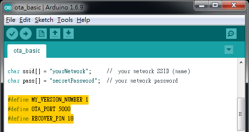
Fill in the ssid and password information in the sample code for network connection.
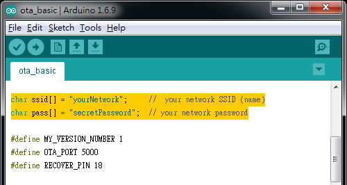
There are some parameters related to OTA:
- MY_VERSION_NUMBER:In first version, we need to set OTA address and recovery pin. Since this time we upload via USB is the first version, we don’t need to change this value.
- OTA_PORT:Arduino IDE will find Ameba via mDNS. Ameba will tell Arduino IDE that it opens TCP port 5000 to wait for OTA image.
- RECOVERY_PIN:Configure the pin used for recovery. We use pin 18 here.
Then we use USB upload program to Ameba. Click Tools -> Ports, check the serial port to use: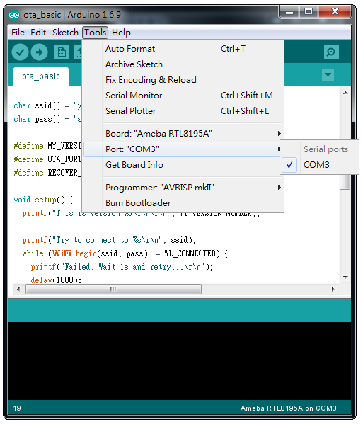
Please note that Arduino IDE uses one port for upload program and output log. To avoid the situation that the log cannot be output when we use OTA, we use other serial port terminal (e.g., Tera term or putty) instead of serial monitor to watch log message.
Then click upload and press reset button.
In the log message:
1. Between “===== Enter Image 1====” and “Enter Image 2 ====”, you can find “Flash Image 2:Addr 0xb000”. This means Ameba determines to boot from Default Image 2 at 0xb000.
2. After “Enter Image 2 ====”, you can find “This is version 1”. This is the log message we add in sketch.
3. After Ameba is connected to AP and gets IP address “192.168.1.238”, it activates mDNS and waits for client.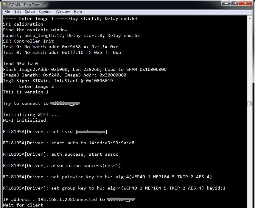
Next, we modify “MY_VERSION_NUMBER” to 2.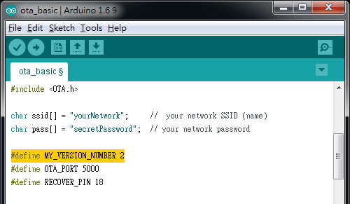
Click “Tools” -> “Port”, you can see a list of “Network ports”. Find “MyAmeba at 192.168.1.238 (Ameba RTL8195A)”, MyAmeba is the mDNS device name we set in sample code, and “192.168.1.238” is the IP of Ameba.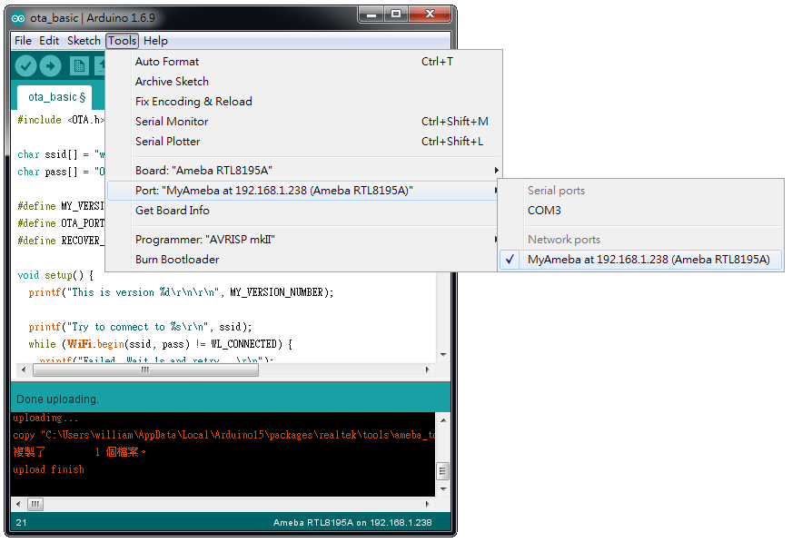
If you cannot find the network port of Ameba, please confirm:
– whether your computer and Ameba are in the same local network?
– try to restart Arduino IDE.
– check log message in Serial Monitor to see whether Ameba is connected to AP successfully.
Then click upload. This time the program will be uploaded via TCP. In the log terminal, you can see client connection information.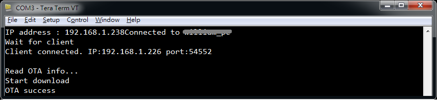
When OTA image is downloaded successfully, Ameba will reboot and following log will be shown in log terminal.
– Between “===== Enter Image 1====” and “Enter Image 2 ====”, you can see a log message “Flash Image 2:Addr 0x80000”. This means Ameba determines to boot from OTA Image at 0x80000.
– After “Enter Image 2 ====”, the log “This is version 2” is the message we add in sketch.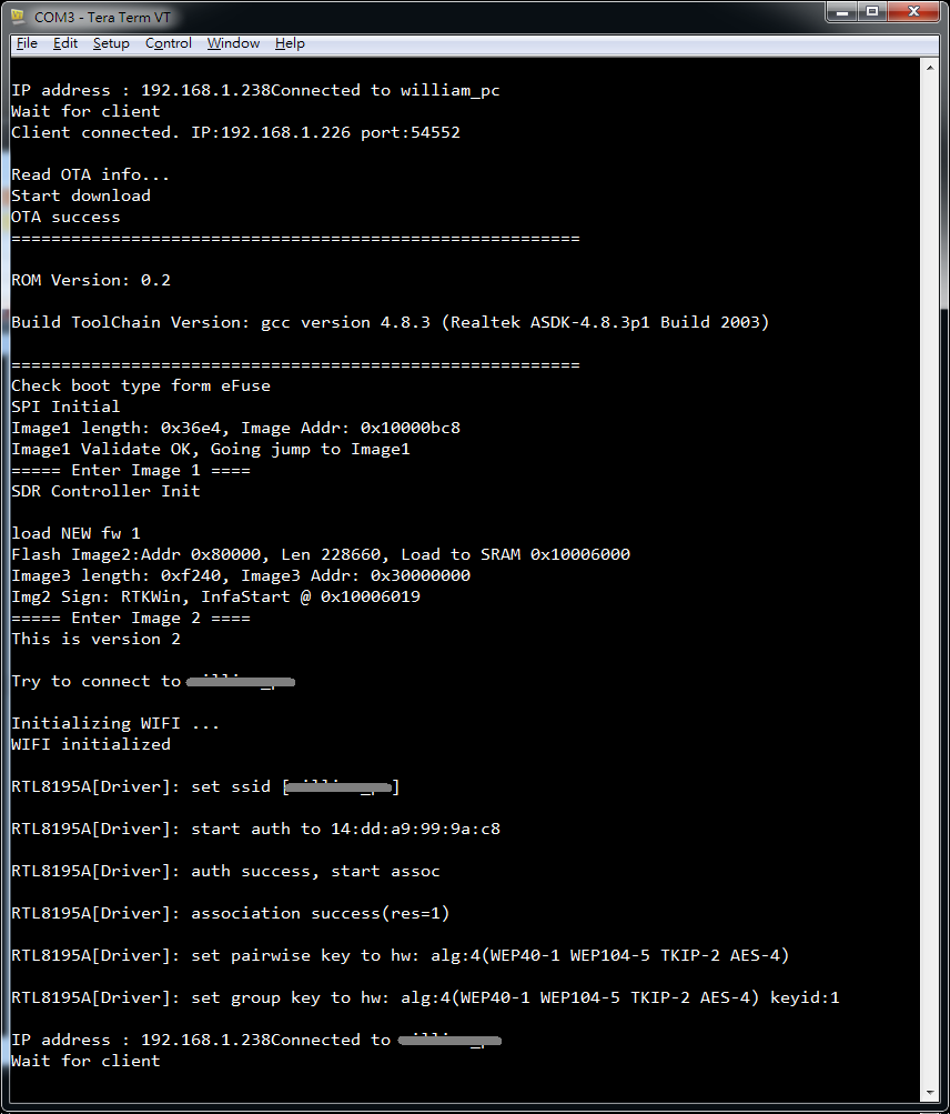
To recover to previous image after OTA image is downloaded to Ameba, please connect the recover pin we set in sketch (i.e., pin 18) to HIGH (3.3V), and press reset.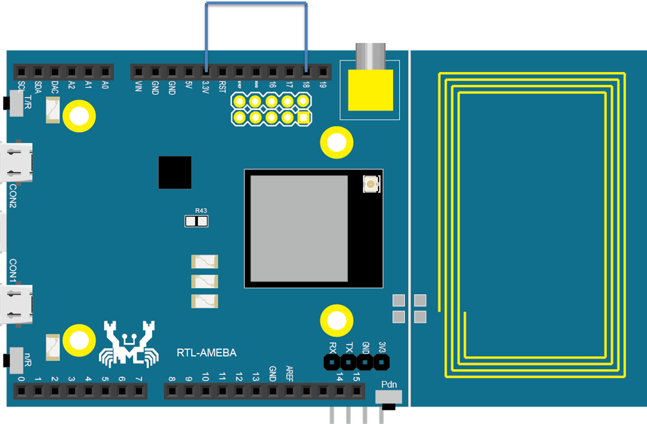
Then Default image 2 will be chosen when booting. Note that the downloaded OTA image is not deleted, once the recovery pin is disconnected from HIGH, the OTA image will be executed.
We summary the development flow using OTA in the following figure: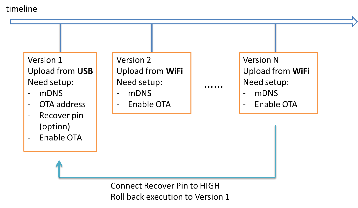
Code Reference
#if MY_VERSION_NUMBER == 1
  OTA.setOtaAddress(DEFAULT_OTA_ADDRESS);
  OTA.setRecoverPin(RECOVER_PIN);
#endif
Use setOtaAddress to wrtie OTA address to system data section in flash memory. The default value is 0x00080000.
OTA.setOtaAddress(DEFAULT_OTA_ADDRESS);
Then set recover pin to a preferred pin.
OTA.setRecoverPin(RECOVER_PIN);
Then begin mDNS service, specify the mDNS device name and the TCP port used in OTA service in the parameters.
OTA.beginArduinoMdnsService("MyAmeba", OTA_PORT);
Finally, begin OTA service and wait for client connection. Ameba will restart when OTA is finished.
OTA.beginLocal(OTA_PORT)
Code Reference(non block)
In this example, the OTA service runs in a separated thread, as shown in below figure:
The main thread starts wifi_service_thread to connect to WiFi and begin ota_thread. And the main thread resumes to execute the application.
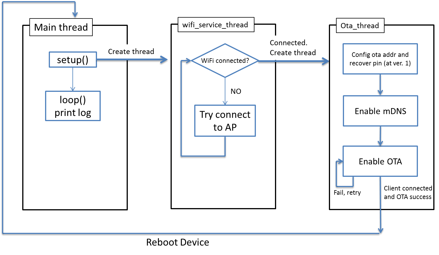
In setup() in main thread we create a thread with the function pointer and the parameters for wifi_service_thread (here we do not need any parameter), the third parameter is the priority of the thread, and the fourth parameter is the memory to use in this thread.
os_thread_create(wifi_service_thread, NULL, OS_PRIORITY_REALTIME, 2048);
OS schedules the execution of main thread and wifi_service_thread.
In the example, Main thread prints log message every second.
wifi_service_thread tries to connect to WiFi, and creates ota_thread once connected. We record the thread id returned by os_thread_create to avoid creating duplicated ota_thread unnecessarily.
ota_thread_id = os_thread_create(ota_thread, NULL, OS_PRIORITY_REALTIME, 2048);
Afterwards, OS schedules the execution of main thread, wifi_service_thread and ota_thread.
wifi_service_thread will keep checking WiFi connection status. If it is disconnected, it tries to reconnect.
ota_thread tries to perform OTA service until success.
