Materials
Example
Introduction
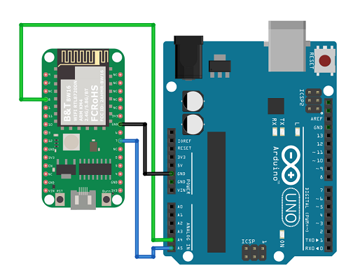
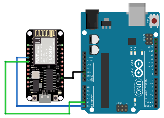
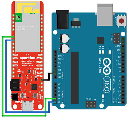
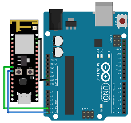
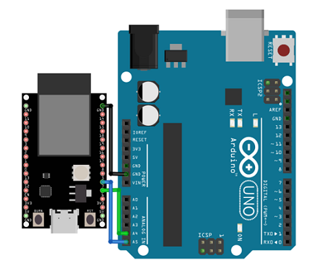
In this example, we use one Ameba RTL8722 modules that connecting with an infrared (IR) Emitter to transmit and receive IR SONY data “0xA90” (Sony TV power code). For the receiver side, you can either use an oscilloscope/logic analyser to view the waveform and decode accordingly.
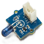
Figure 1: Grove – Infrared Transmitter
On the transmission side, the transmitter will send IR SONY data. For more details, please refer to SB-Projects’ topic of IR Remote Control Theory to learn the theory of IR remote controls operation and a collection of IR protocol descriptions. In this example, we are going to use Sony as the transmission protocol.
Sony Features
• 12-bit version, 7 command bits, 5 address bits.
• Pulse width modulation.
• Carrier frequency of 40kHz.
• Bit time of 1.2ms or 0.6ms.
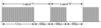
Sony SIRC Modulation
The SIRC protocol uses pulse width encoding of the bits. The pulse representing a logical “1” is a 1200us long burst of the 40kHz carrier, while the burst width for a logical “0” is 600us long. All bursts are separated by a 600us long space interval as shown in Figure 2 below.
Figure 2: Sony SIRC Modulation
Protocol
Figure 3: 12-bit Sony SIRC protocol
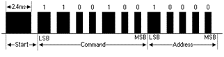
The Figure 3 above shows a typical pulse train of the 12-bit SIRC protocol. With this protocol the LSB is transmitted first. The start burst is always 2.4ms wide, followed by a standard space of 0.6ms. Apart from signalling the start of a SIRC message this start burst is also used to adjust the gain of the IR receiver. Then the 7-bit Command is transmitted, followed by the 5-bit Device address. In this case Address 1 and Command 19 is transmitted.
Commands are repeated every 45ms (measured from start to start) for as long as the key on the remote control is held down.
Procedure
After the connection is being set up correctly, we will move to the coding part for this example. First, make sure the correct Ameba development board is selected in Arduino IDE: “Tools” -> “Board”.
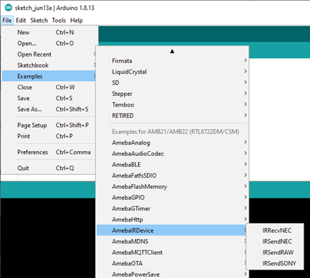
Open the “IRSendSONY” example in “File” -> “Examples” -> “AmebaIRDevice” -> “IRSendSONY” (Figure 9) and upload to the board connected with IR Emitter:
Figure 9: Example Location of IRSendSONY
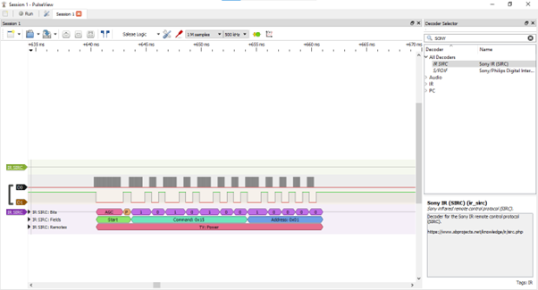
After successfully upload the sample code for IRSendSONY, you could use oscilloscope or Pulse View software to find out the waveform of the signal transmitted from the IR Emitter is “0xA90” as shown in Figure below:
Code Reference
[1] Seed Official website for Grove – Infrared Emitter
https://wiki.seeedstudio.com/Grove-Infrared_Emitter/
[2] Ken SHirriff’s blog on A Multi-Protocol Infrared Remote Library for the Arduino
http://www.righto.com/2009/08/multi-protocol-infrared-remote-library.html
[3] SB-Projects: IR Remote Control Project
https://www.sbprojects.net/knowledge/ir/index.php
[4] SONY SIRC Protocol
https://www.sbprojects.net/knowledge/ir/sirc.php
