Introduction
Realtek RTL8720DN is a Wi-Fi and Bluetooth IC that supports 2.4GHz and 5GHz dual bands for Wi-Fi communication, and Bluetooth Low Energy (BLE) 5.0. BW16 module is manufactured by B&T, this module is a highly integrated Wi-Fi and Bluetooth module with the RTL8720DN as the main SoC (System on Chip), it can be regarded as an SoC for the Wi-Fi and Bluetooth application with typical SBCs. BW16 board is a development board that integrated with the module. There are 2 BW16 boards, BW16 and BW6-TypeC. BW16 board uses Micro USB connector.
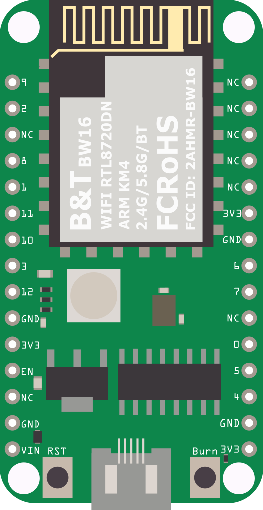
BW16 board
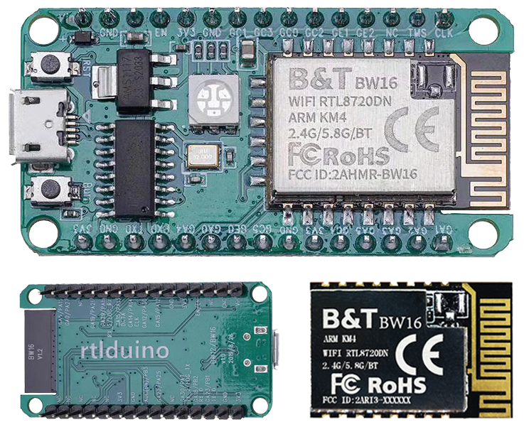
The size of the board is 50.4*25.4(±0.2) mm. It uses Micro USB to supply power, which is common in many smart devices.
Please refer to the following figure and table for the pin diagram and function.
BW16 Pinmap
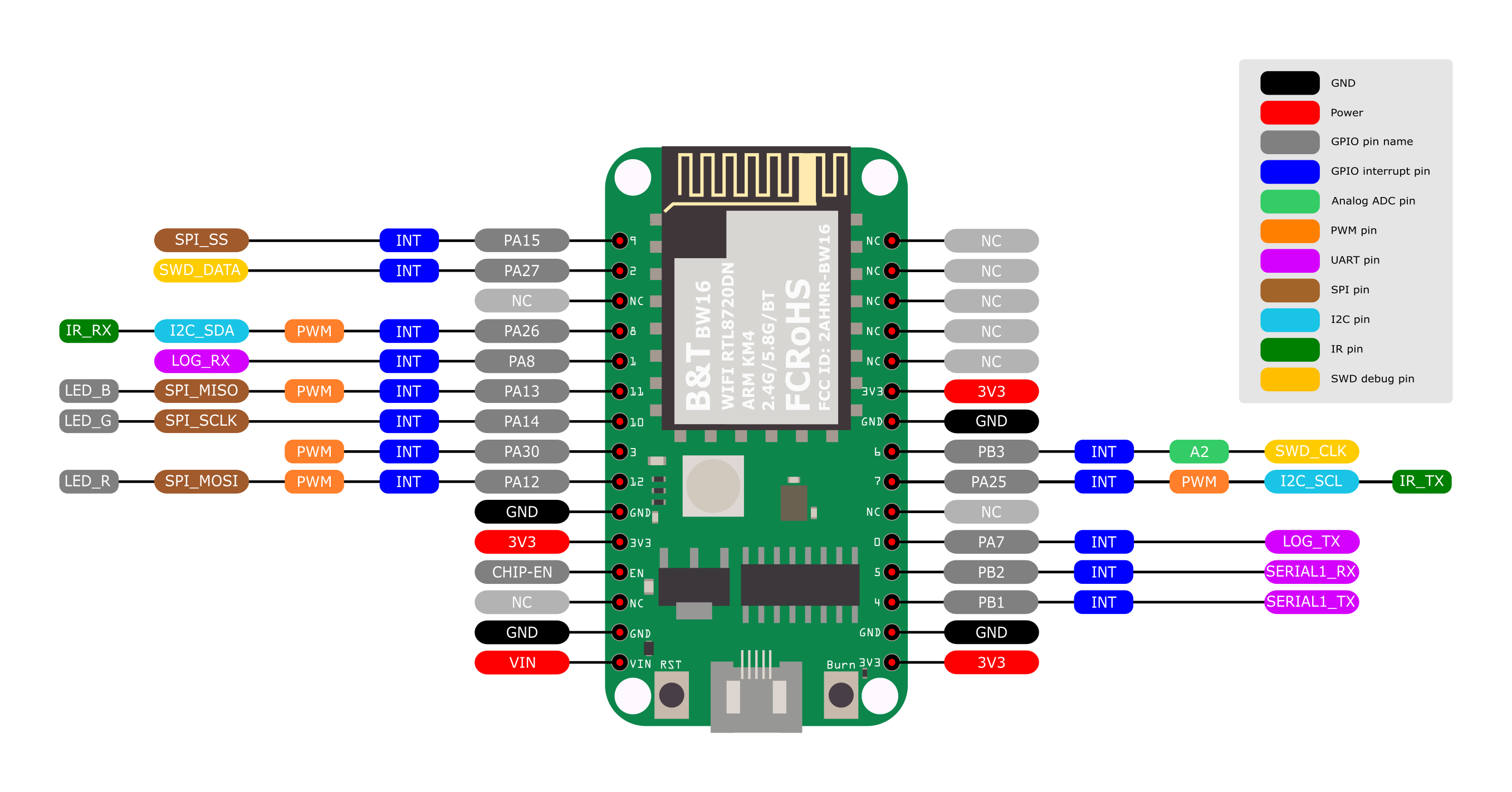
| GPIO pin | GPIO INT | ADC | PWM | UART | SPI | I2C | IR | RGB LED | SWD | |
| 0 | PA7 | ✓ | LOG_TX | |||||||
| 1 | PA8 | ✓ | LOG_RX | |||||||
| 2 | PA27 | ✓ | SWD_DATA | |||||||
| 3 | PA30 | ✓ | ✓ | |||||||
| 4 | PB1 | ✓ | Serial_TX | |||||||
| 5 | PB2 | ✓ | Serial_RX | |||||||
| 6 | PB3 | ✓ | A2 | SWD_CLK | ||||||
| 7 | PA25 | ✓ | ✓ | I2C_SCL | IR_TX | |||||
| 8 | PA26 | ✓ | ✓ | I2C_SDA | IR_RX | |||||
| 9 | PA15 | ✓ | SPI_SS | |||||||
| 10 | PA14 | ✓ | SPI_SCLK | LED_G | ||||||
| 11 | PA13 | ✓ | ✓ | SPI_MISO | LED_B | |||||
| 12 | PA12 | ✓ | ✓ | SPI_MOSI | LED_R |
There are 2 buttons besides USB connector. “RST” button is on the left and “Burn” button is on the right as shown on above figures. Refer the following table for the functions of the buttons.
| Button Functions | Button Process |
| Reset board | Press then release “RST” |
| Enter upload mode | Press and hold “Burn” Press then release “RST” Release “Burn” |
The Upload Mode is required by board when erase flash or upload firmware.
Set up developing environment
Step 1. OS environment
BW16 (RTL8720DN) board currently supports Windows OS 32-bits or 64-bits, Linux OS (Ubuntu) and macOS. To have the best experiences, please use the latest version of OS.
For any Linux OS (Ubuntu) related issues, refer to https://forum.amebaiot.com/t/ubuntu-linux-environment/2259.
For any macOS related issues, refer to https://forum.amebaiot.com/t/macos-environment/2260.
Step 2. Set up Arduino IDE
From version 1.6.5, Arduino IDE supports third-party hardware. Arduino IDE is used to develop applications on BW16, and the Arduino basic examples (refer to the basic example link).
Arduino IDE can be downloaded in the Arduino website: https://www.arduino.cc/en/Main/Software
When the installation is finished, open Arduino IDE. Go to “File” -> “Preferences”.
And paste the following URL into the “Additional Boards Manager URLs” field: https://github.com/ambiot/ambd_arduino/raw/master/Arduino_package/package_realtek_amebad_index.json
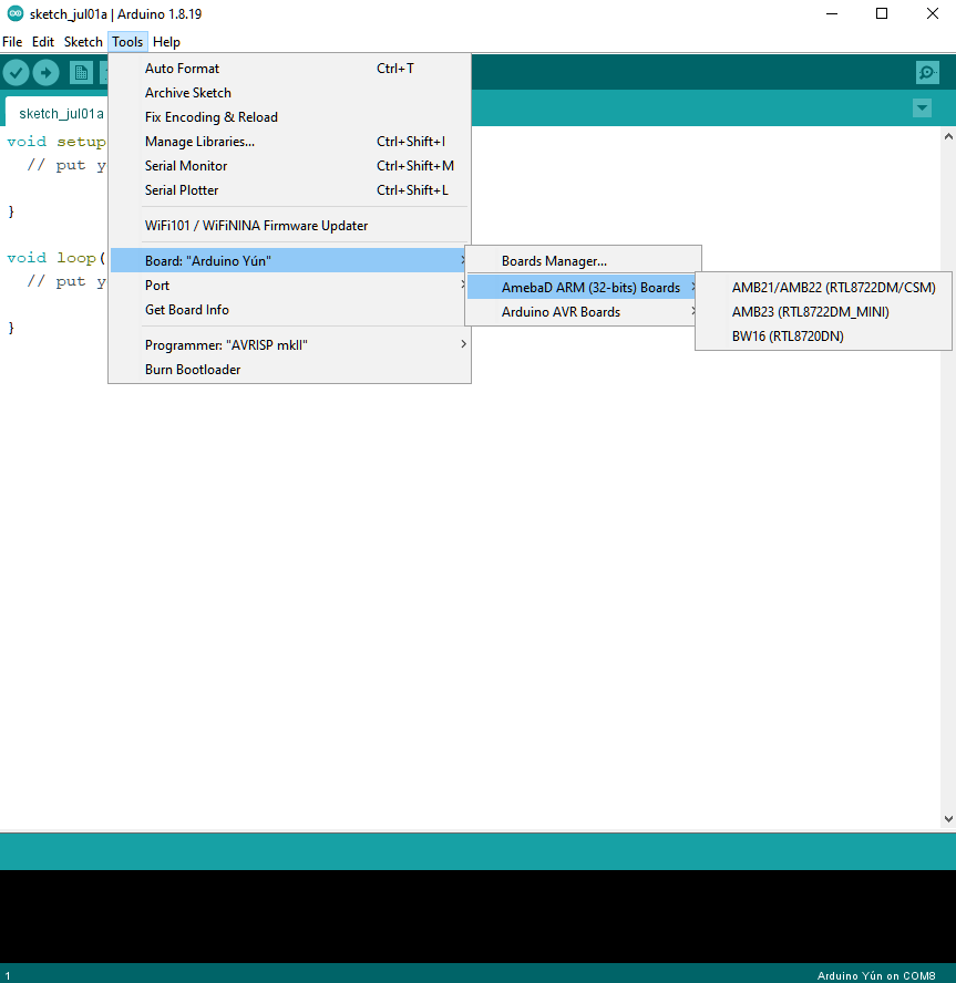
Next, go to “Tools” -> “Board” -> “Boards Manager”:
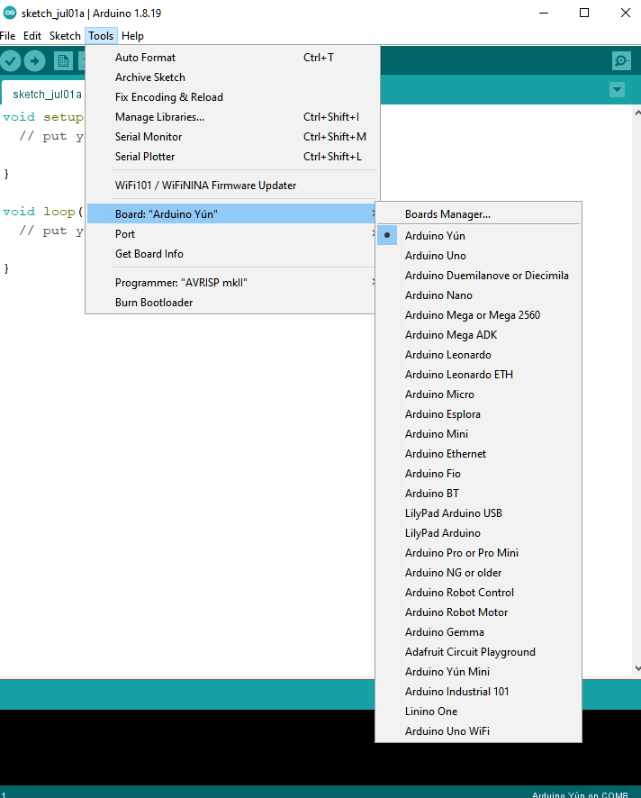
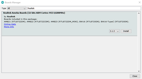
The “Boards Manager” requires several seconds to refresh all hardware files (if the network is in bad condition, it may take longer). Search “Realtek” then find “Realtek Ameba Boards (32-bits ARM Cortex-M33 @200MHz)” in the list, click “Install”, then the Arduino IDE starts to download required files for AmebaD family includes BW16.
If there is downloading issue (Bad internet or GitHub access), please refer to the following link at “Download/Software Development Kit”. There are 3 sections.
1. “AmebaD_Arduino_patch1_SDK”, please select at least 1 of the SDKs. There are 5 latest released SDK options.
2. “AmebaD_Arduino_patch2_Tools”, please select according to operating system. There are Windows, Linux, and macOS.
3. “AmebaD_Arduino_Source_Code”, this section is optional. Download for the latest source code.
Download the files selected, then unzip (patch1 and patch2 are compulsory). There are “Install.doc”/“Install.pdf” for you to refer to installation steps. According to your system, please run the installation tool in the “Offline_SDK_installation_tool” folder.
After the installation, select AmebaD as current connected board in “Tools” -> “Board” -> “Ameba ARM (32-bits) Boards” ->” BW16(RTL8720DN)”:
Step 3. Install the Serial port
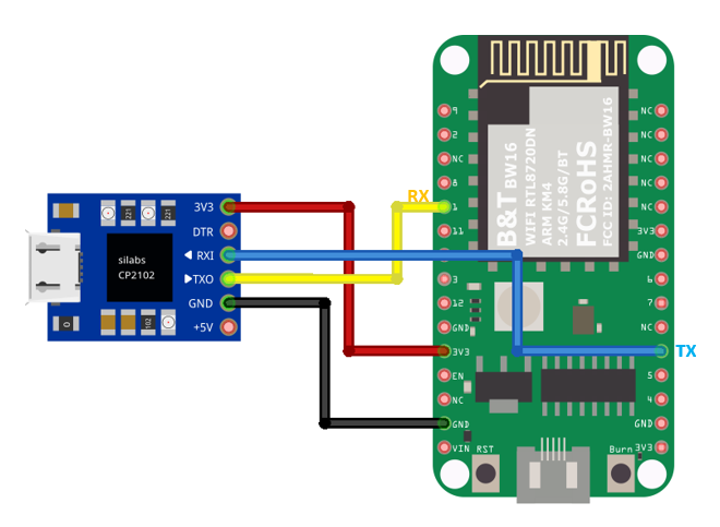
First, connect the board to computer via Micro USB:
BW16
Refer to the pinmap and table above, D0 and D1 pins are used for program uploading. However, onboard USB-to-UART module is connected to D4 and D5 which is not able to be directly used for program upload. In order to upload firmware, it suggests that adding an external USB-to-UART module connecting to D0 and D1 as shown in the pin connection below:
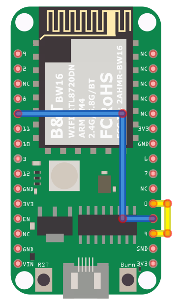
Optionally, short the pins indicated below to use the on-board USB:
D1 ––– D5
D0 ––– D4
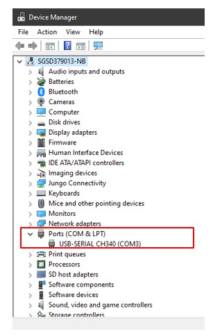
After connected, the USB driver will be automatically installed. If there is any driver issue of connecting board, please go to http://www.wch-ic.com/downloads/CH341SER_ZIP.html for USB driver. Check the COM Port number in Device Manager for Windows OS user:
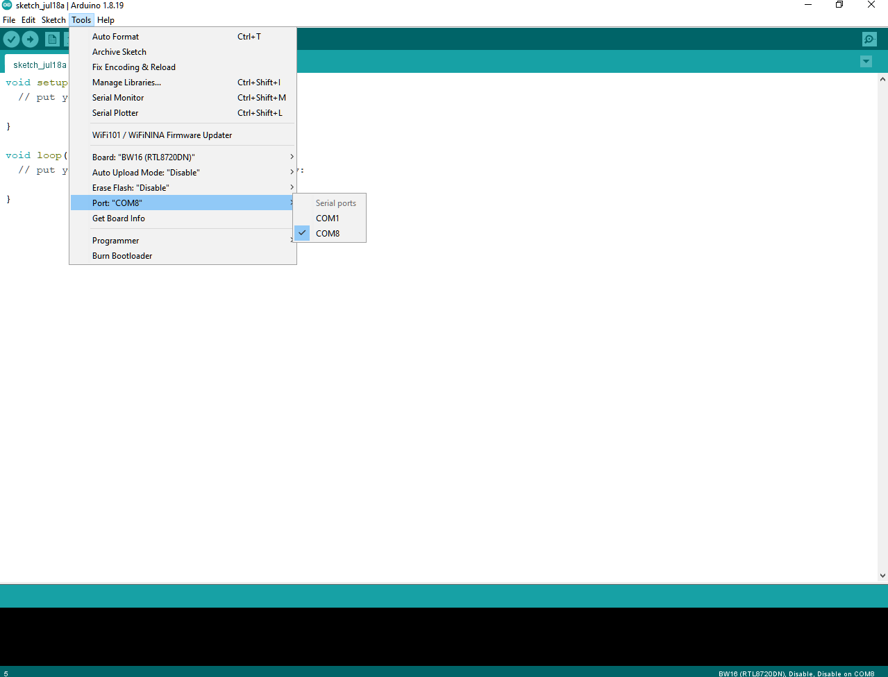
Go to “Tools” -> “Port” and select the correct COM port.
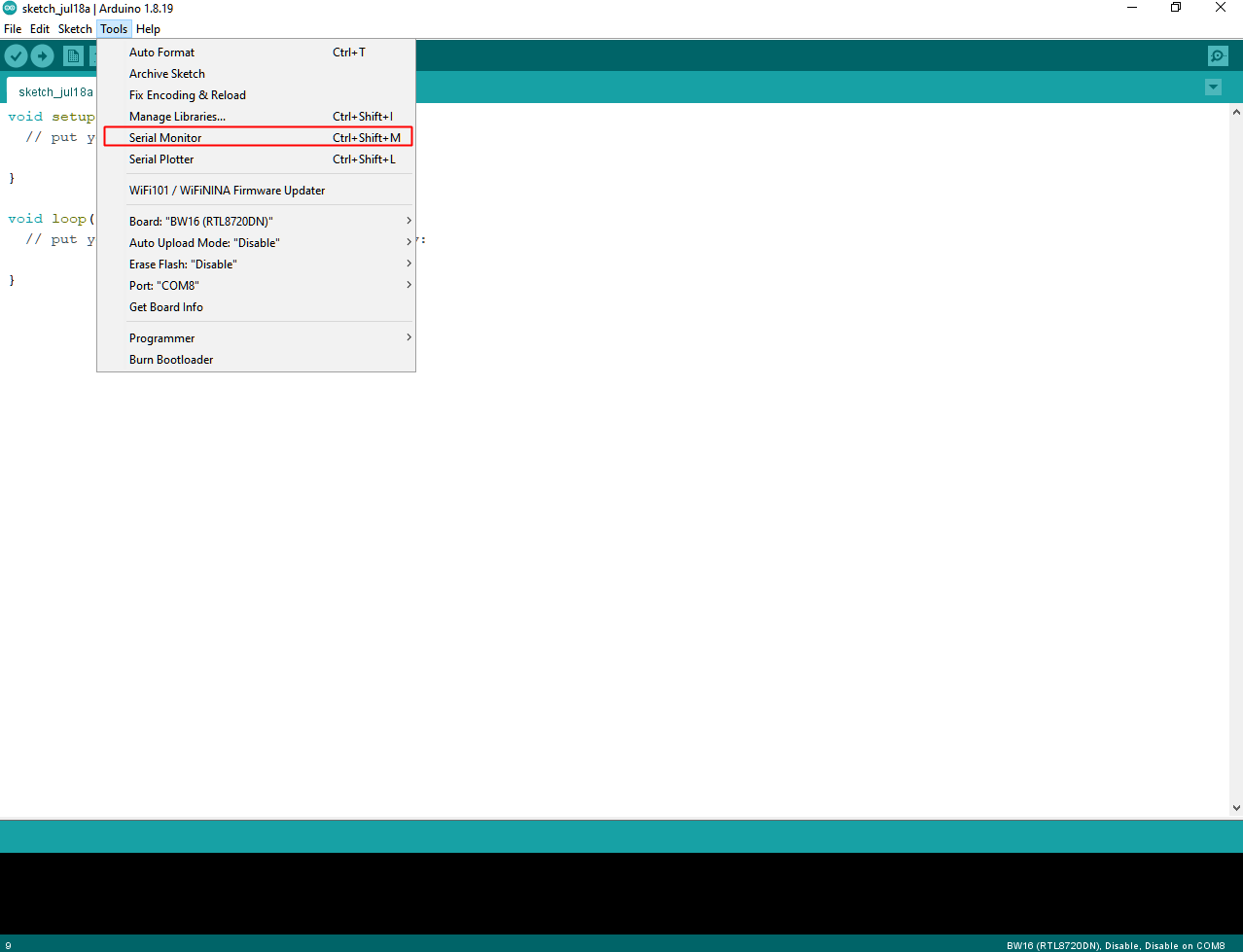
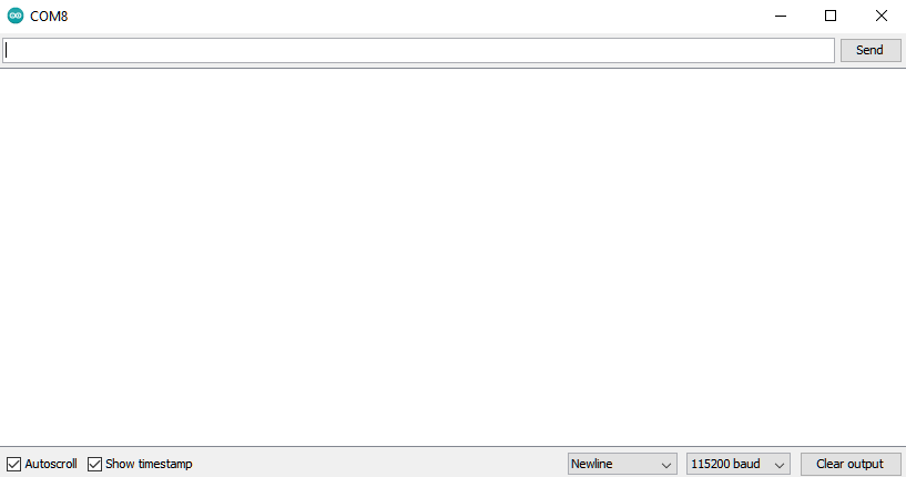
Go to “Tools” -> “Serial Monitor”, set the baud rate as “115200”, and press the RST button to check the serial port connection.
Step 4. Erase flash
Depending on the batch of manufacturing, some boards might have built-in the default B&T firmware, the firmware information is shown below:
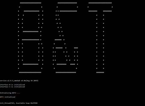
The firmware is at the OTA section. All new compiled firmware will be replaced automatically by the OTA section firmware. Therefore, OTA section firmware needs to be erased first to make use of compiled firmware.
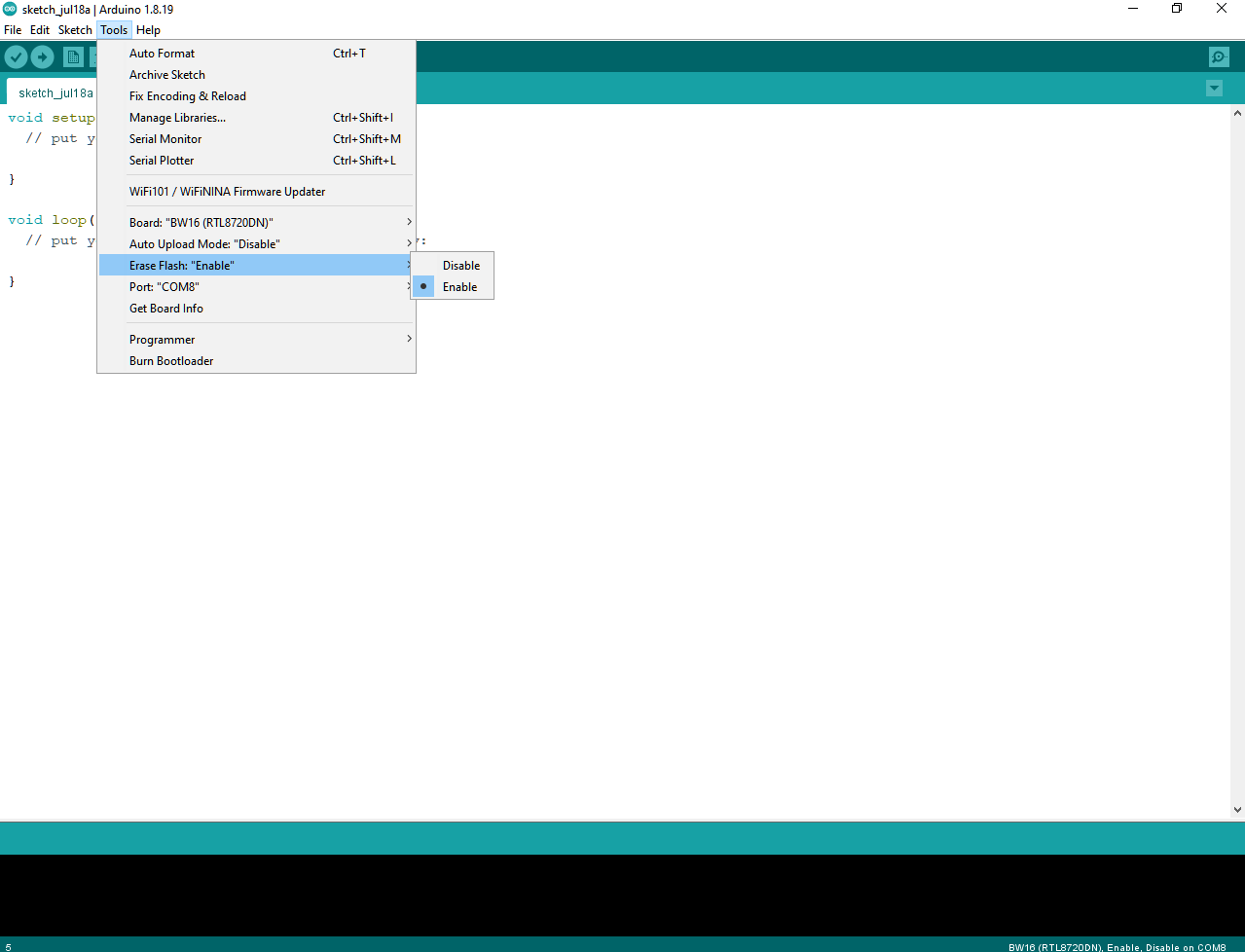
Method 1: “Erase Flash Enable” by Arduino SDK after V3.1.3.
Select “Tools” -> “Erase Flash” -> “Enable”
Then enter the upload mode.
• Manually. Press and hold “Burn” button, press then release “RST” button and release “Burn” button.
• Auto. Select “Tools” -> “Auto Upload Mode” -> “Enable”. Note that only boards with auto upload circuit build-in (BW16-TypeC) can use the Auto Upload Mode, otherwise it will back to normal upload mode and wait for 5 seconds.
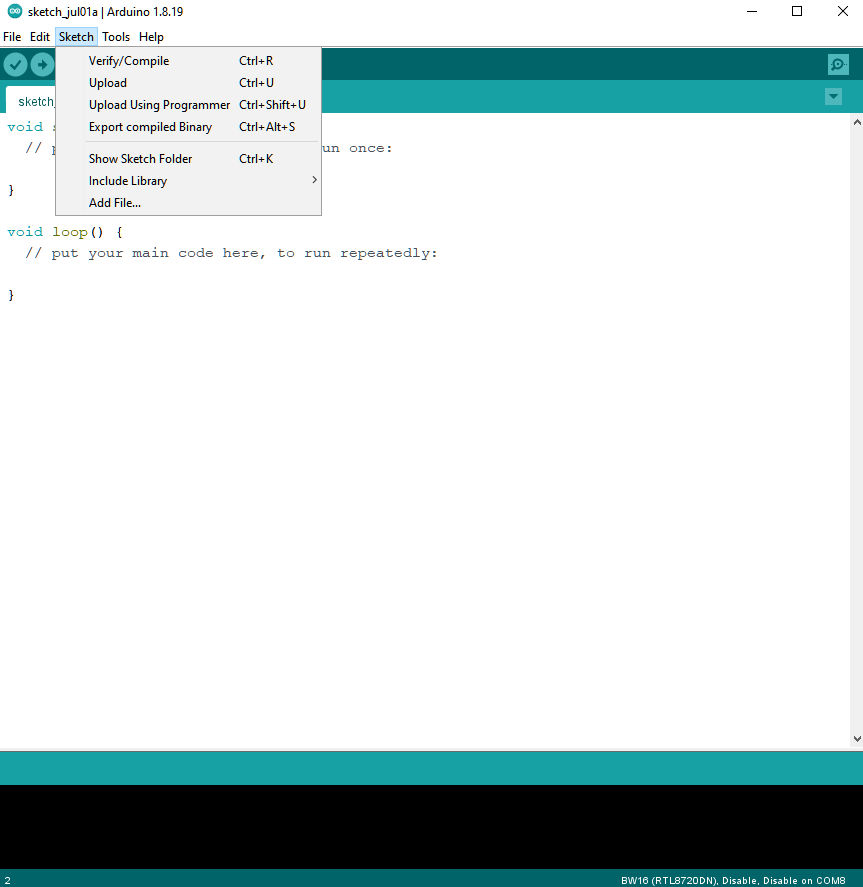
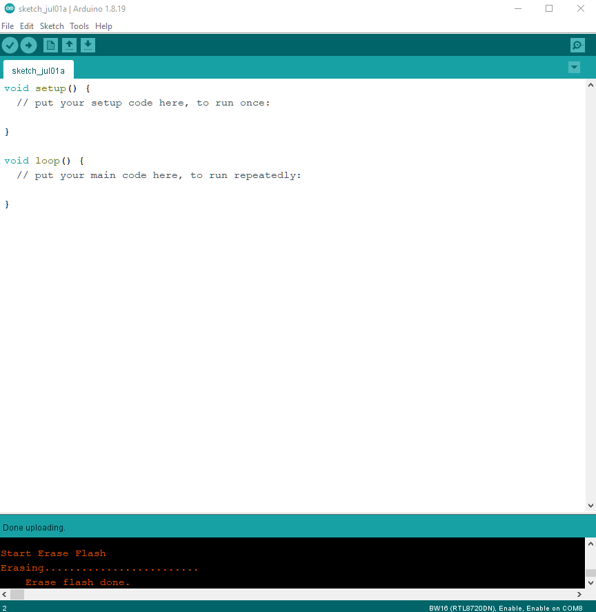
Next, Select “Sketch” -> “Upload”. “Erase flash done.” will show up.
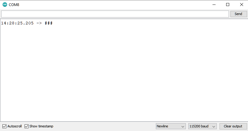
Check the serial monitor and reset board by press RST button. If only “#” shows that means erase flash success. Remember to select “Tools” -> “Erase Flash” -> “Disable”.
Try the First Example
Step 1. Compile & Upload
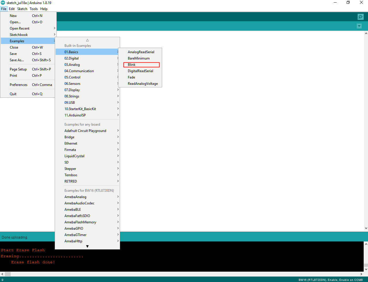
Arduino IDE provides many built-in examples, which can be compiled, uploaded, and run directly on the boards. Here, we take the “Blink” example as the first try.
Open “File” -> “Examples” -> “01.Basics” -> “Blink”:
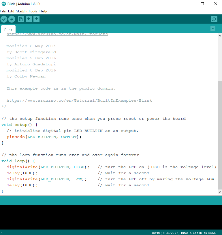
There is an onboard RGB LED, the default “LED_BUILTIN” is green color. Change “LED_BUILTIN” to “LED_R”, “LED_G”, or “LED_B” for red, green, or bule colors.
Next, compile the sample code directly. “Sketch” -> “Verify/Compile”. Then if there is no compile error, followed by “Sketch” -> “Upload”.
• Check and select “Tools” -> “Erase Flash” -> “Disable”.
• Enter the Upload Mode. Manual or Auto. Select “Tools” -> “Auto Upload Mode” -> “Enable”/ ”Disable”.
• “Verify/Compile” and “Upload”. “Upload” includes “Verify/Compile”, “Verify/Compile” can be skipped.
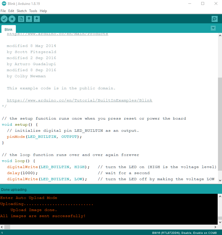
Successful upload will show “All images are sent successfully!”
Step 2. Run the Blink example
The board will be reset automatically, press RST button if board does not support Auto Upload Mode. And the onboard RGB LED will blinking.
In each example, Arduino not only provides sample code but also detailed documentation, including wiring diagram, sample code explanation, technical details, …etc. These examples can be directly used on BW16. Refer to detailed information of the Blink example in the link below:
https://www.arduino.cc/en/Tutorial/BuiltInExamples/Blink
Tool Feature
Erase Flash
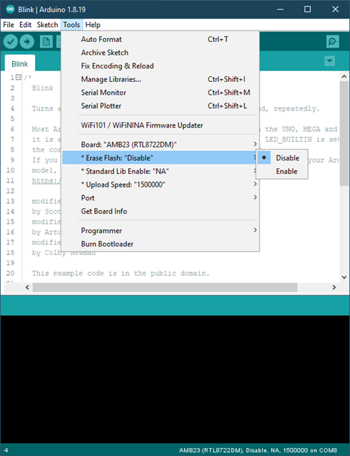
• Enable: erase the image in the flash memory without uploading the current image.
• Disable: upload the user code upon compilation is finished.
“Erase Flash” is default selected as “Disable” to upload the user code.
Standard Lib Enable
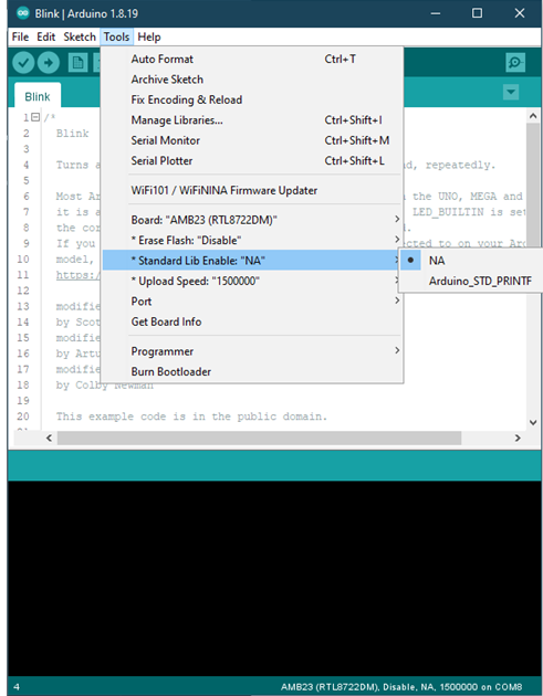
• Arduino_STD_PRTINF: enable the usage of Arduino avr “stdio.h” and “#include ” when using printf
• NA: printf() is using based on standard sdk _rtl_printf()
“Standard Lib Enable” is default selected as “NA”.
Upload Speed
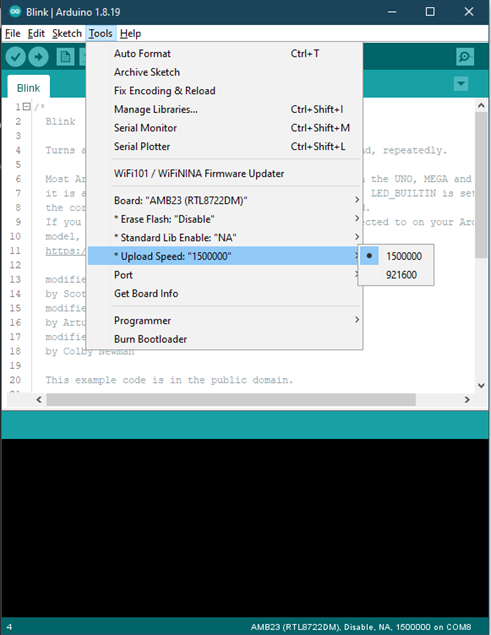
Selection of uploading baud rate at 1,500,000 or 921,600.
References
1. Introduction of RTL8720DN on Instructable:
https://www.instructables.com/RTL8720DN/
2. Load Arduino image into BW16:
How to load BW16 program with Arduino – #13
3. RTL8720DN (BW16) IMG2 SIGN Invalid Solution:
RTL8720DN(BW16) IMG2 SIGN Invalid Solution
4. FTDI Driver Download from here:
https://ftdichip.com/wp-content/uploads/2021/02/CDM21228_Setup.zip
