Function Description
- I/O pin multiplexer
Take for an example, the following table is Pin Function Table for 8195A.
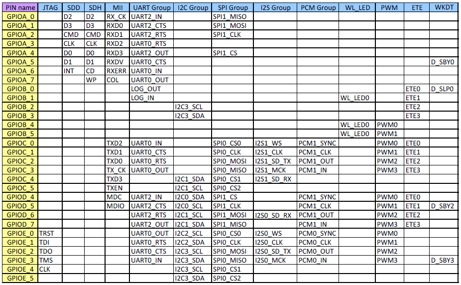
Note 1: Function Pin is enabled via entire group, the un-used pin cannot be disabled separately. Ex: if using debugger in SWD mode, the pin: JTAG_TRST, JTAG_TDI and JTAG_TDO cannot be used as GPIO at the same time.
Note 2: Only SPI0 CS0/CS1 can be separately configured as GPIO even if SPI0 is used at same time. Therefore, user can employ SPI0 in PC_0 ~ PC_4( or PE_0 ~ PE_4), while configuring PC_4(PE_4) and PC_5(PE_5) as GPIO function.
Interrupt configuration
The type of interrupt is programmable with one of the following settings:
- Active-high and level
- Active-low and level
- Rising edge
- Falling edge
Please check example gpio_level_irq to check how to set interrupt type.
/* High Level Trigger */
gpio_irq_set(&gpiol, IRQ_HIGH, 1);

/* Low Level Trigger */
gpio_irq_set(&gpiol, IRQ_LOW, 1);
Please check example gpio_irq to check how to set interrupt type.
/* Rising Edge Trigger */
gpio_irq_set(&gpio, IRQ_RISE, 1);

/* Falling Edge Trigger */
gpio_irq_set(&gpio, IRQ_FALL, 1);