Required Environment
Currently, Ameba RTL8710AF currently supports Windows XP/7/8 32 and 64 bits, Linux ubuntu and MAC OS operating systems. In this example, please use Arduino IDE with version 1.8.12 or later.
Introduction to Ameba RTL8710
Ameba RTL8710 is similar to Ameba RTL8195, both are suitable for developing all kinds of IoT applications. Ameba is equipped with various peripheral interfaces, including WiFi, GPIO, I2C, UART, SPI and so on. It can connect with common components and modules of Arduino via these interfaces. Unlike Arduino, it can upload data to cloud through built-in WiFi directly to realize IoT implementation.
Compared to RTL8195, RTL8710 lacks some GPIO and some functions like SDIO, UVC, NFC, ADC, DAC, etc. However, RTL8710 is cheaper than RTL8195. Users can choose suitable platform to meet own requirements.
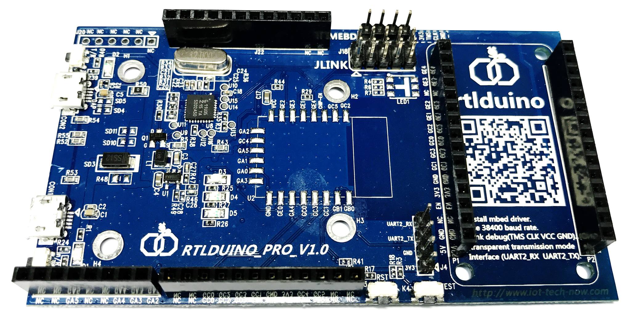
RTL8710 board is compatible and similar to Arduino UNO and its size is the same with RTL8195 board. It uses micro usb to charge on the left and the module on the right is removable. As a result, users can employ smaller space to do wiring and assembly after the development.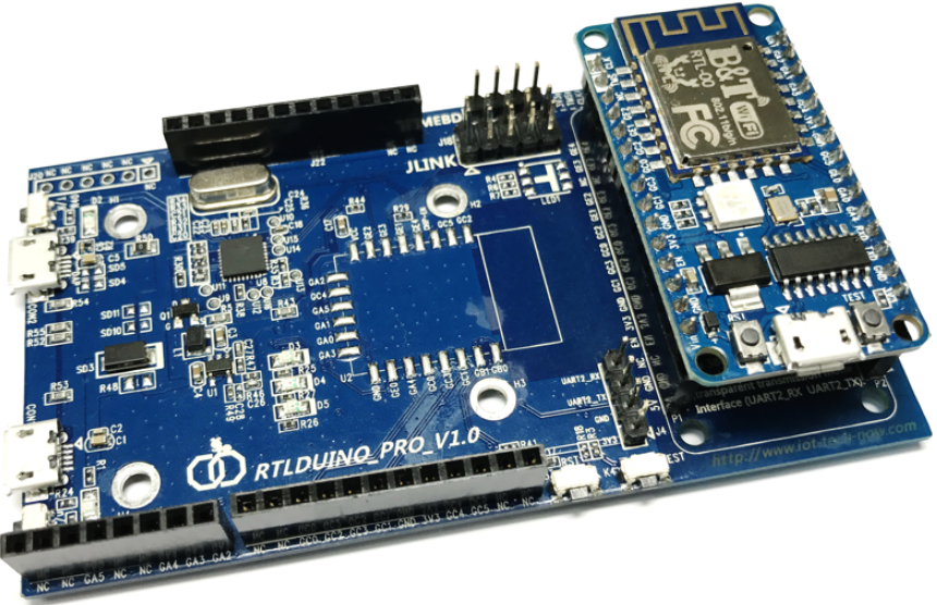
The dismantled module is shown below, and the model is RTL-00. It also uses micro usb to charge and the pins on it are compatible with the board.
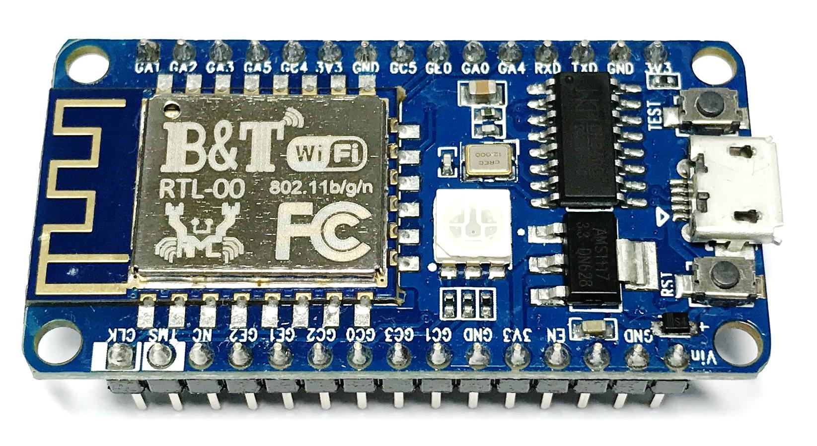
The main board can be used with other RTL-00 modules
Setting up Development Environment
Step 1. Installing MBED Driver
If you had already installed RTL8195A before, then you can skip this chapter and go to “Setting up Arduino IDE”
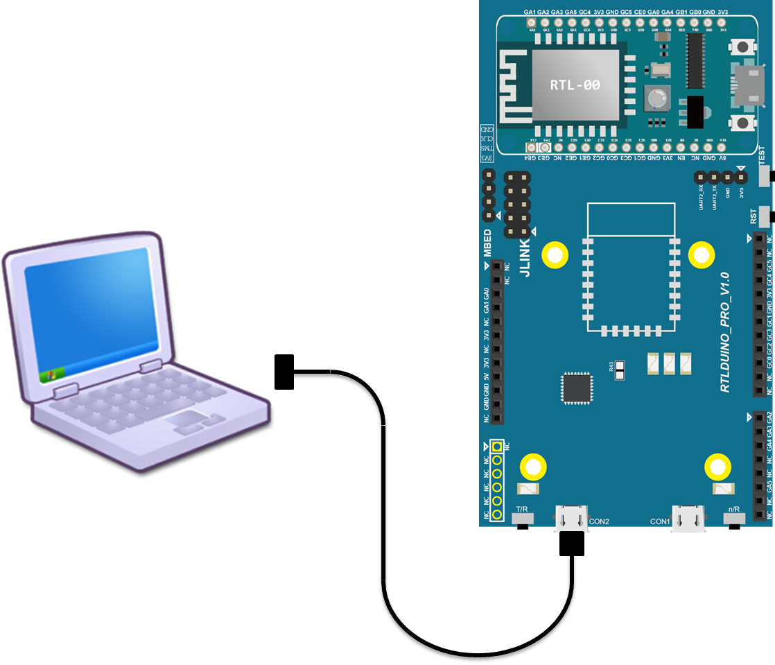
First, connect RTL8710 to the computer via Micro USB:
If this is the first time for you to connect Ameba to your computer, you have to install the USB driver for Ameba. Ameba uses the standard Arm MBED CMSIS DAP driver, you can get the installation file and related information on the following website:
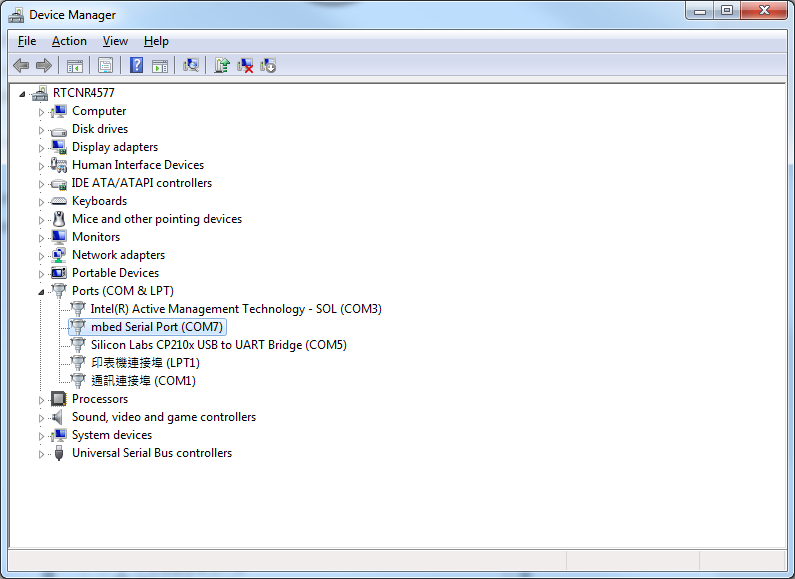
Download and install “mbedWinSerial_16466.exe” in “Download latest driver”. Afterwards, you will see “mbed Serial Port” in Device Manager of your computer:
Step 2. Set up Arduino IDE
From version 1.6.5, Arduino IDE supports third-party hardware. Therefore, we can use Arduino IDE to develop applications on Ameba, and the examples of Arduino can run on Ameba too. Arduino IDE can be downloaded on the Arduino website:
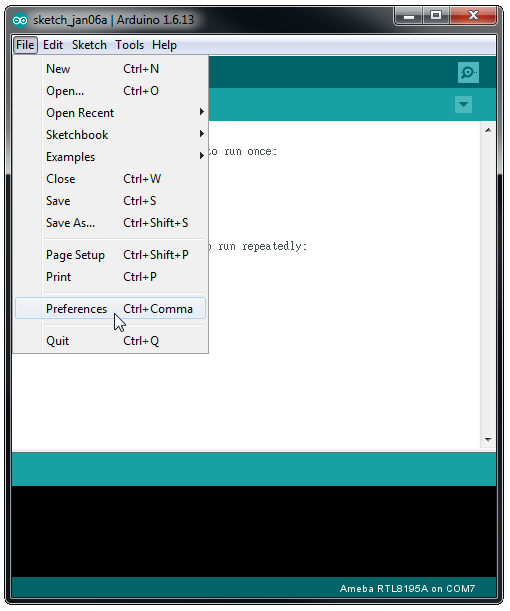
Open Arduino IDE after the installation. In order to let Arduino IDE find out Ameba configuration file. Go to “File” -> “Preferences”
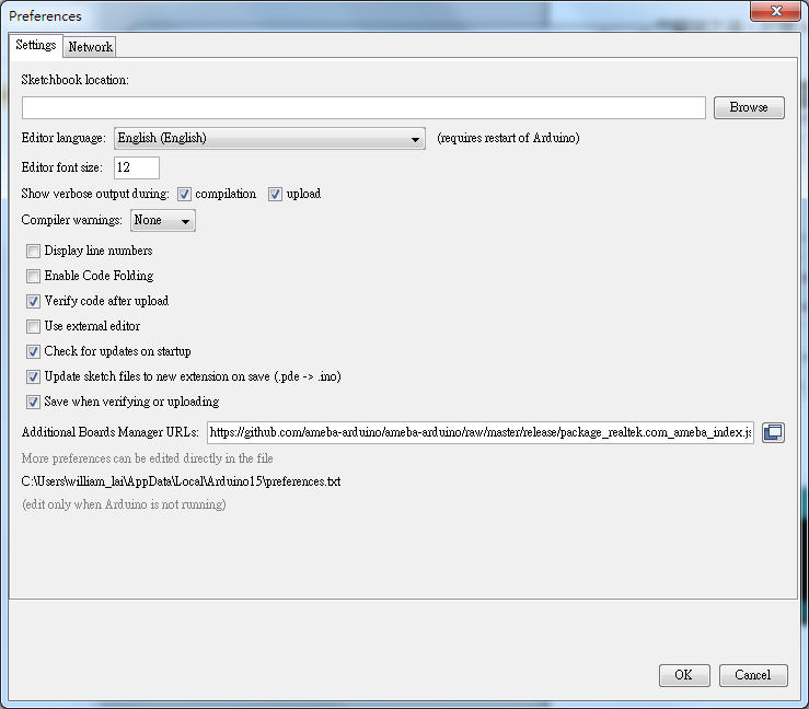
And paste the following URL into “Additional Boards Manager URLs” field:
Arduino Ameba package v1.0.0 to v2.0.5
https://github.com/Ameba8195/Arduino/raw/master/release/package_realtek.com_ameba_index.jsonArduino Ameba package v2.0.6 and above
https://github.com/ambiot/amb1_arduino/raw/master/Arduino_package/package_realtek.com_ameba1_index.jsonMoreover, if the IDE version you use is earlier than 1.6.7, please make sure the IDE language is set to English to avoid language problem.
In version 1.6.7, Arduino has resolved the language problem.
Please restart the Arduino IDE to activate the setting.
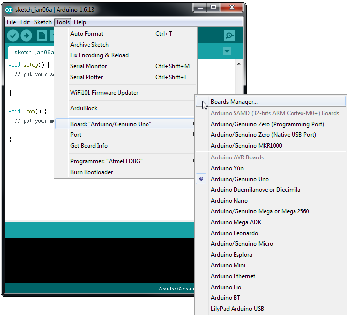
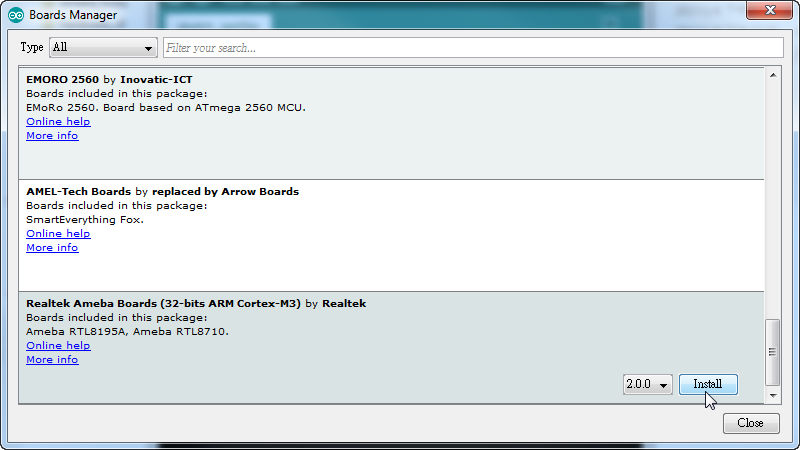
Next, go to “Tools” -> “Board” -> “Boards Manager”:
The “Boards Manager” requires about 10~20 seconds to refresh all hardware files (if the network is in bad condition, it may take longer). Every time the new hardware is connected, we need to reopen the Board Manager. So, we close the Boards Manager, and then open it again. Find “Realtek Ameba Boards” in the list and it supports Ameba RTL8710 after the version 2.0.0, click “Install”, then the Arduino IDE starts to download required files for Ameba.
Then select Ameba as current connected board in “tools” -> “Board” -> “Ameba RTL8710″:
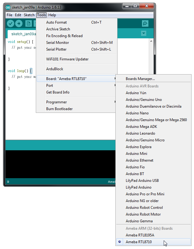
Finish the development environment setting.
Try the First Example
Step 1. Compile & Upload
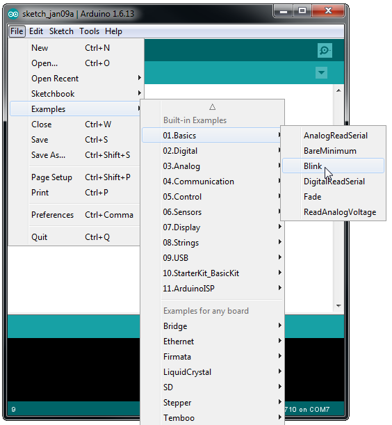
Arduino IDE provides many built-in examples, which can be compiled, uploaded and run directly on the boards. Here, we take the “Blink” example as the first try.
Open “File” -> “Examples” -> “01.Basics” -> “Blink”
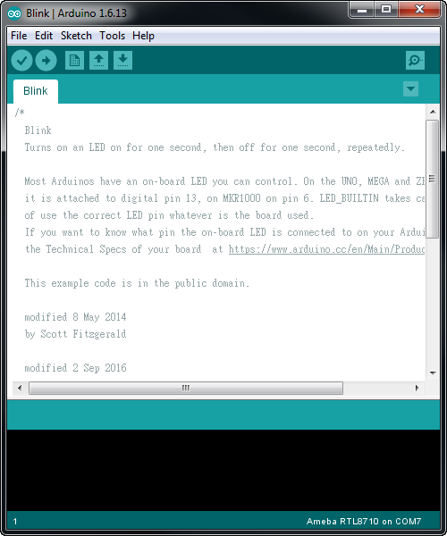
Arduino IDE opens a new window with the complete sample code.
There are some brief explanation on the top of the sample code. Take “Blink” as the example, it indicates that if you use UNO, MEGA, ZERO then you have to connect to pin 13. And the Ameba setting is the same with the UNO setting in this example.
Next, we compile the sample code directly, click “Sketch” -> “Verify/Compile”
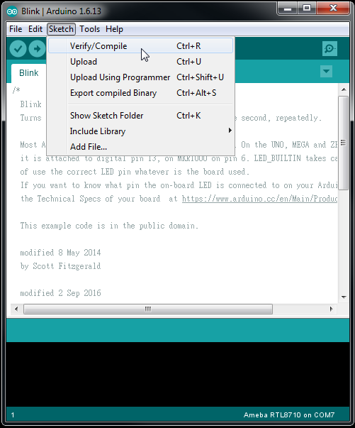
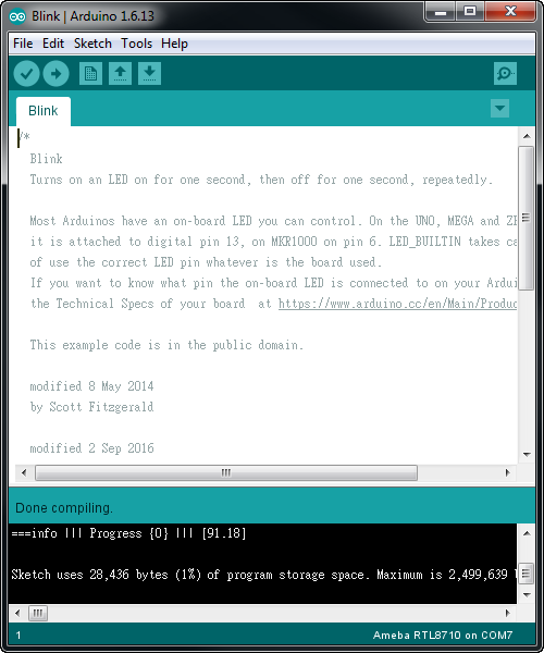
Arduino IDE prints the compiling messages in the bottom area of the IDE window. When the compilation is finished, you will get the similar messages shown below:
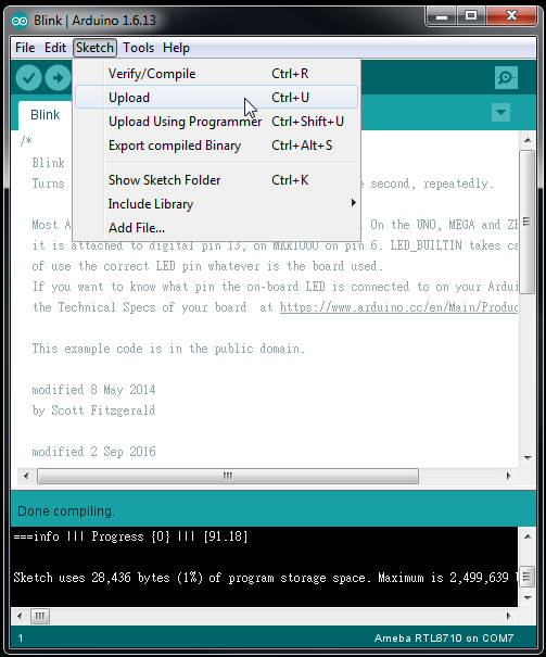
Afterwards, we will upload the compiled code to Ameba. Please make sure Ameba is connected to your computer, then click “Sketch” -> “Upload”
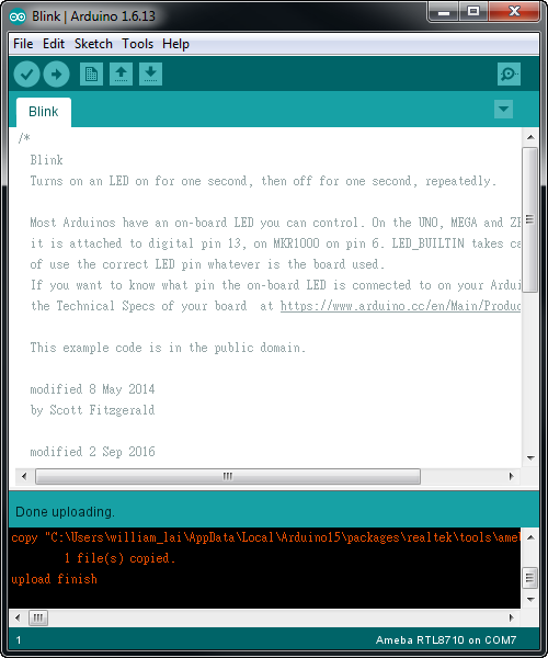
Again, during the uploading procedure the IDE prints messages. Uploading procedure requires respectively longer time (about 30 seconds to 1 minute). When upload completed, the “upload finish” message is printed.
Step 2. Run the Blink example
Ihis Blink example makes LED blink and it uses GPIO pin 13.
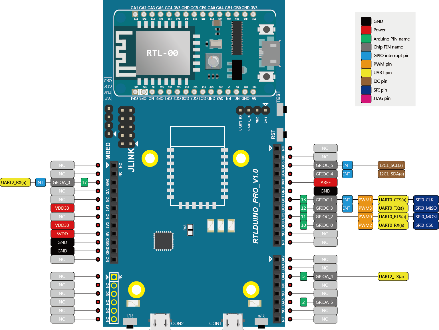
Refer to RTL8710 pinout:
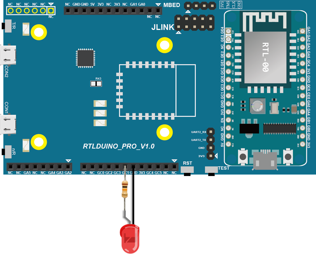
Then we connect the LED and resistance as the following figure:
(NOTE: In an LED, the longer pin is the positive pole, and shorter pin is the negative pole. So we connect the longer pin to D13, and connect the shorter pin to GND.)
Finally, press the reset button, and you can see the LED blinking.
If you encounter any problem, please refer to Trouble-shooting
Step 3. Use module RTL-00 independently
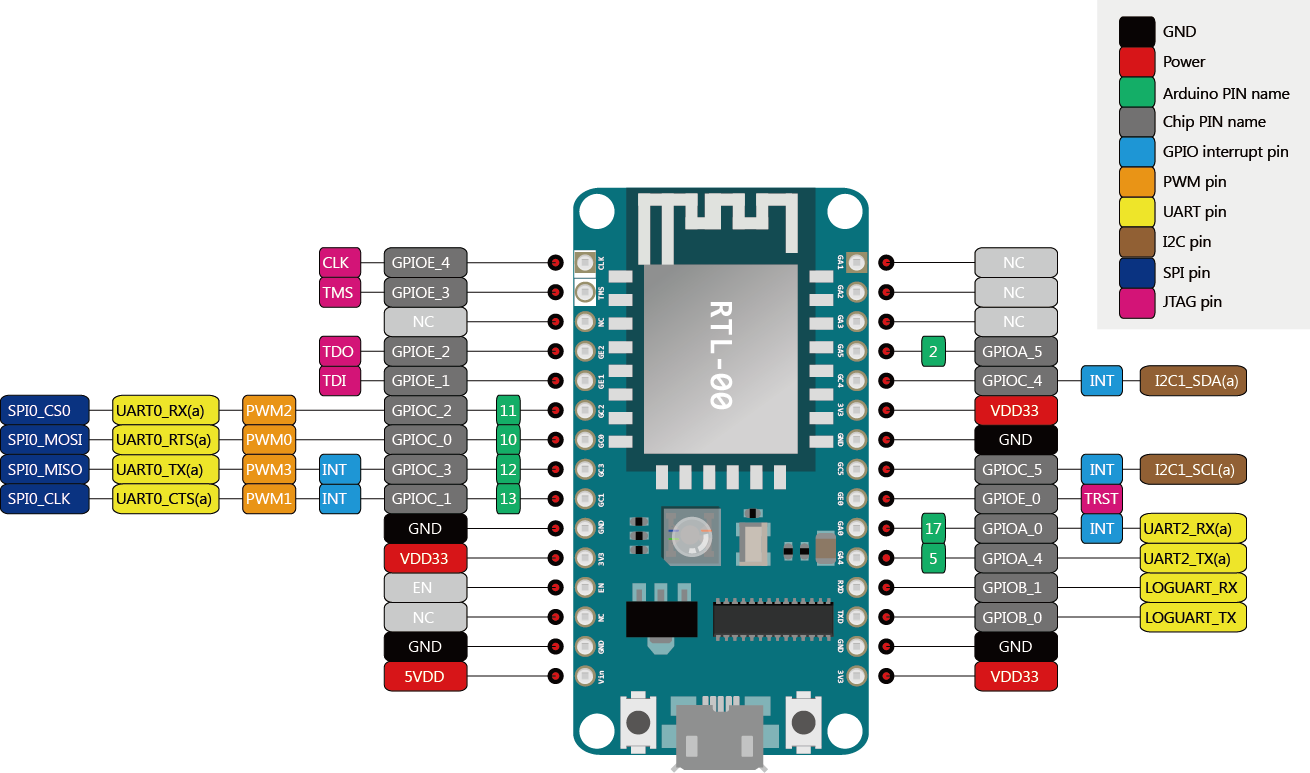
RTL-00 module can be used independently from the main board, and the occupied space is smaller. Remove the RTL-00 module on the right and you can refer to the RTL-00 module pinout:
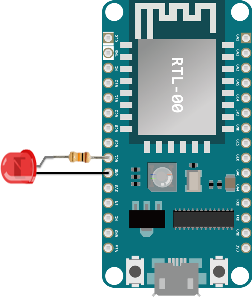
And the wiring is shown below
Charge it via the Micro USB on the bottom, and the result should be the same with connecting to the main board.